


Basic Knowledge of RS485 Communication
Add Date: 2019-7-6 Views: 21338
1. 485 communication
1.1. Communication connection
1.1.1. Interface definition:
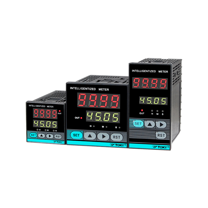
Intelligent digital display instruments generally adopt RS485 communication interface mode, generally three terminals: A+, B-, COM. As shown in Figure 1:
When there are multiple 485 communication devices on one bus, the connection should be hand-in-hand. The maximum recommended number of devices on a bus is no more than 32 devices. Figure 2
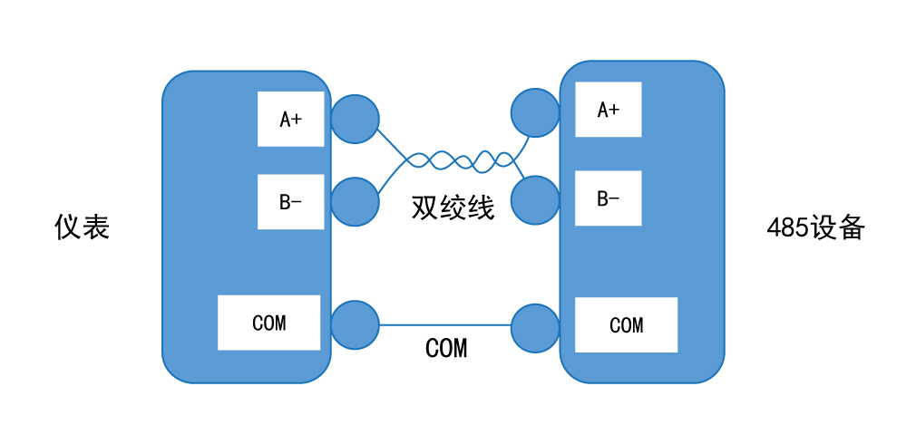
Figure 1: 485 communication wiring method
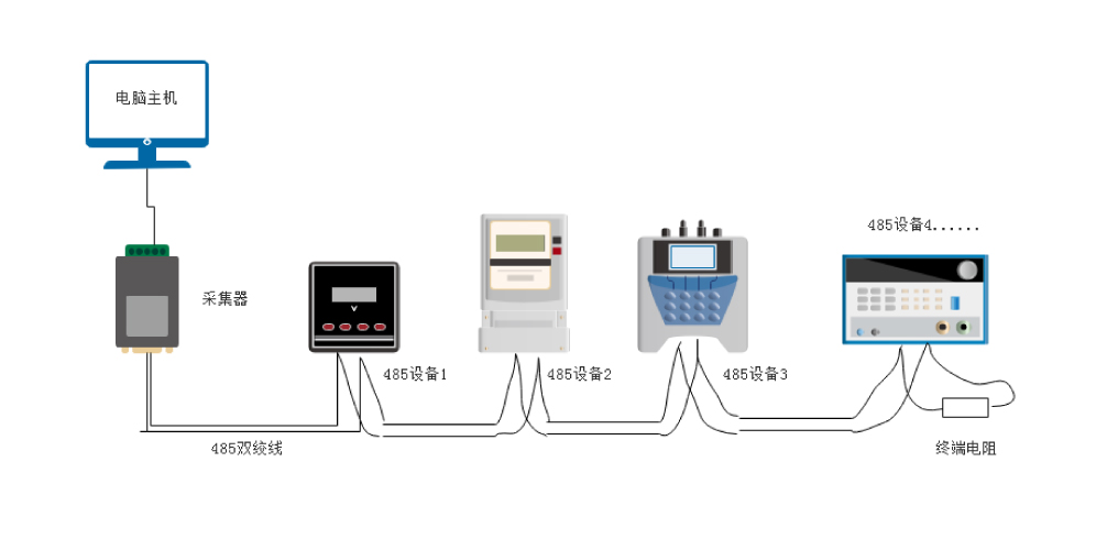
Figure 2: 485 bus connection for multiple devices
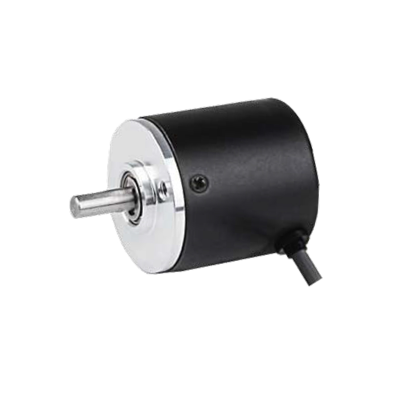
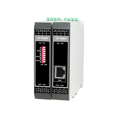
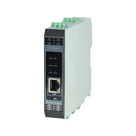
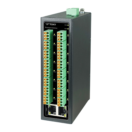
1.1.2. Communication Interface and Converter
Since the instrument adopts the RS485 communication interface, the common PLC, touch screen, etc. all have this interface. However, this interface is generally not available on computers. When communicating with a computer, interface conversion is required. Common devices include: USB to RS485 converter, RS232 to RS485 converter, Ethernet to RS485 serial server, communication management machine, etc. Figure 3:
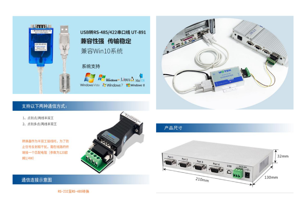
Figure 3: Common Serial Converter
1.2. Communication settings
1.2.1. Protocol: The instrument supports the standard Modbus-RTU serial communication protocol; refer to relevant national standards: GB/T 19582.1-2008, GB/T 19582.2-2008;
1.2.2. The data transmission format is: 1 bit start bit, 8 data bits, 1 stop bit, no parity bit.
1.2.3. General setting of the instrument Factory default: ADD address: 1, baud rate: 9600, CRC check: N
1.2.4. Data Byte Order: H-L (high first, low last)
1.2.5. Data format: integer (32-bit long integer, 16-bit short), 32-bit floating-point float. According to different series of instruments.
1.3. Register Address
1.3.1. The register address in our company's manual, also called variable address or address mapping table, is represented by hexadecimal address code. For example, 0X2000 means hexadecimal address 2000. 32-bit data occupies 2 register positions (4 words) Section), 16-bit data occupies 1 register position (2 bytes). The 32-bit data address indicates the register position occupied by each parameter with addresses such as 0, 2, 4, 6, ...; 16-bit data is represented by addresses 0, 1, 2, 3, ... The register location occupied by each parameter.
As shown in Figure 4 below:
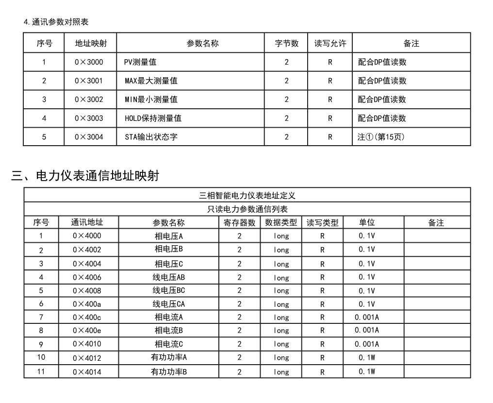
Figure 4: Parameter list of sensor table and power meter
1.3.2. When the computer reads the data, it reads the corresponding data from the above variable address. When the computer communicates with the instrument, the upper computer directly accesses the data in hexadecimal data; however, most industrial control configuration software, monitoring system software, PLC, touch screen, etc. need to be converted to decimal address code for reading.
As shown in Figure 5, Figure 6, and Figure 7, read the phase A voltage value starting from 0X4000, you need to convert 0X4000 to decimal number to get 16384, then use 400001+16384=416385
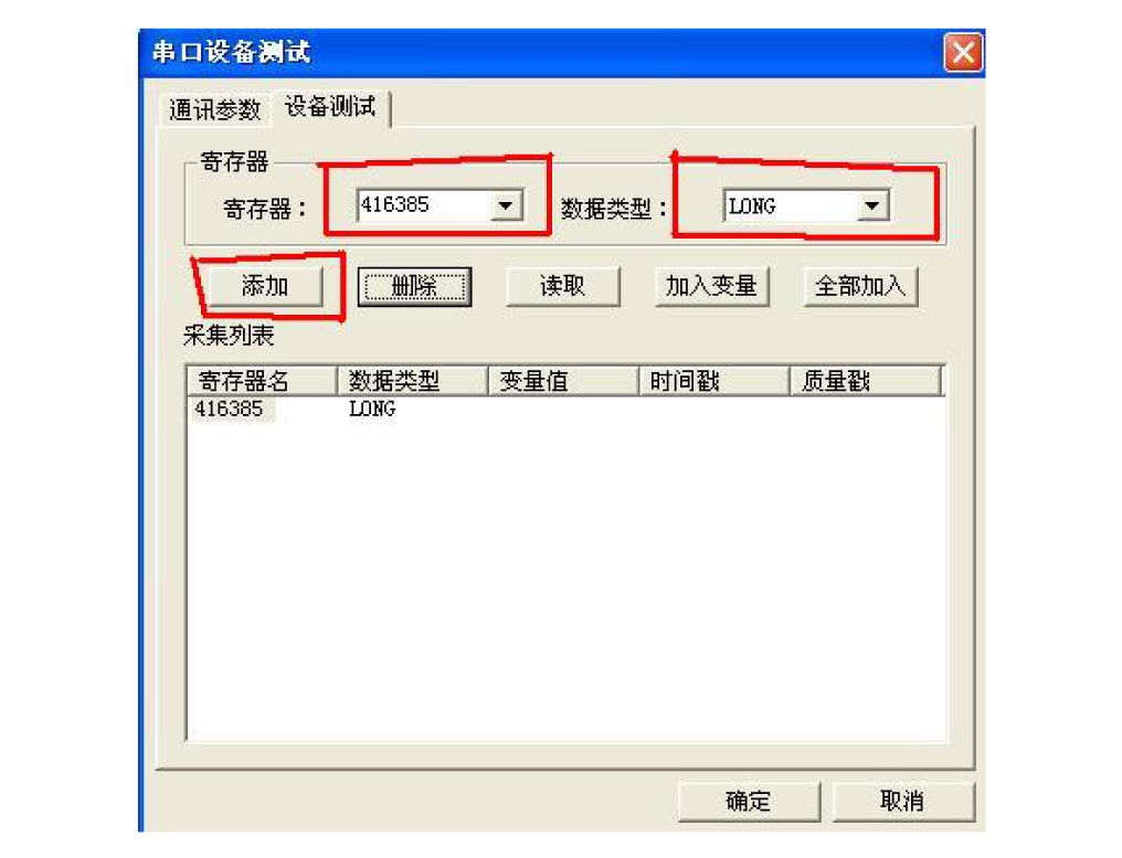
Figure 5: Register address setting during configuration king serial device test
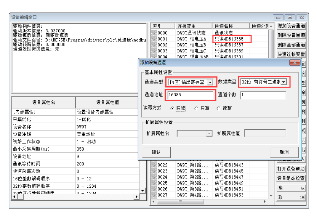
Figure 6: Kunlun open state touch screen device channel acquisition settings
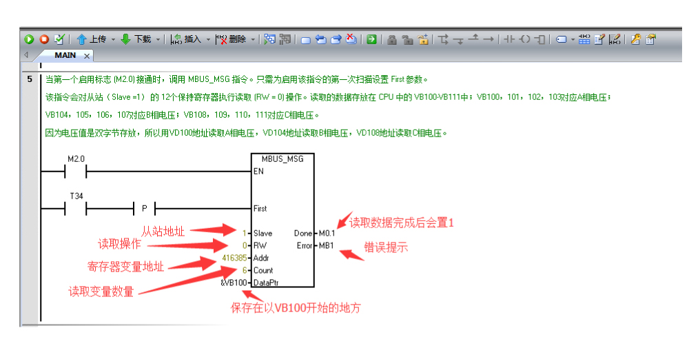
Figure 7: Siemens s7-200smart PLC read command settings
1.4.1. The meter is generally sent with hexadecimal data. After the host computer receives the data, it needs to perform data conversion processing. The commonly used ones are generally long, short, and floating. Long long integer data is 32 bits, occupying 2 registers, 4 bytes; short short integer data is 16 bits, occupies 1 register, 2 bytes; float floating point type is 32 bits of data, occupying 2 registers and 4 bytes .
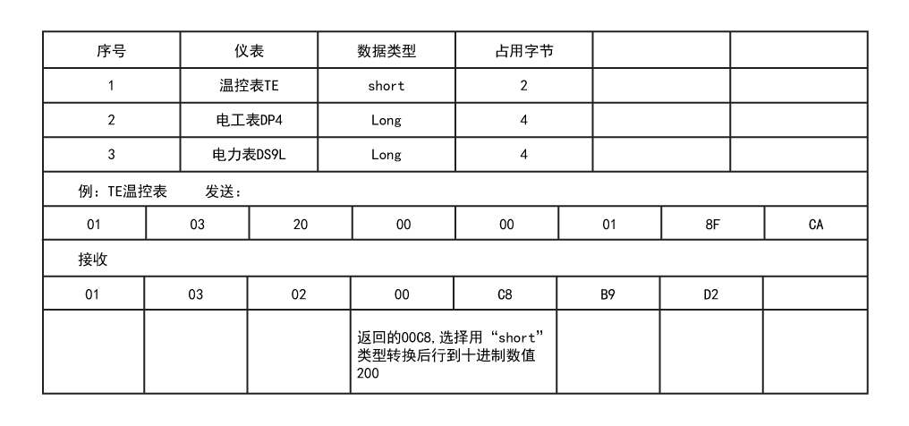
1.4.2. When the upper computer processes the data, it needs to be converted according to the actual data type of the product. The following table is an example:
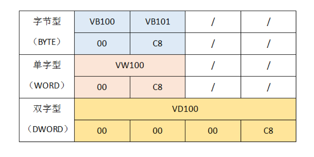
1.4.3. PLC storage area data description
Let the read data be stored in the V memory area starting with VB100, then for different types of data such as long\short\float, it should be converted according to the type defined by PLC:
1.5. Display processing
1.5.1. After the integer data is converted to decimal, the decimal point needs to be processed. The magnification conversion of the decimal point can be performed according to the manual. Generally, the integer of the converted decimal number is multiplied by the number of decimal places. Such as:
2. Brief introduction of Modbus-RTU communication protocol
2.1. Introduction
The Modbus protocol is a standard protocol for the industrial control industry. It is divided into two protocols, one is the Modbus-RTU serial protocol and the other is the Modbus-TCP network port protocol.
The Modbus protocol was developed for Modicon and was later acquired by Schneider and is now a standard protocol for Schneider. The modbus protocol has been widely used in industrial control and has become a common industry standard that supports rs-232, rs-422, rs-485 and Ethernet devices. The control devices produced by different manufacturers can be connected to the communication network through the modbus protocol for centralized monitoring. Many industrial products, such as plc, inverters, human-machine interfaces, dcs, and automated smart meters, are widely used in the modbus protocol.
According to the type of transmission network, it is divided into modbus on serial link and modbus based on tcp/ip protocol.
The Modbus serial link protocol is a master-slave protocol. In the request-response mode, the master station sends a request message with a slave address, and the slave station with the address sends a response message to respond.
In the Modbus protocol, there is only one master station in an RS-485 serial bus, which can have 1 to 247 slave stations. Modbus communication can only be initiated by the primary station. When the secondary station does not receive a request from the primary station, it will not send data and the secondary stations will not communicate with each other.
2.2. Modbus message transmission mode---RTU mode
The rtu mode message on the Modbus network is transmitted in bytes, and one byte consists of two hexadecimal numbers. Each byte transmitted contains a start bit, 8 data bits (send the lowest valid bit first), the parity bit, the stop bit are the same as the ascii mode, and the message length is up to 256 bytes.
The last two bytes of the Modbus rtu mode message are the cyclic redundancy check code (crc). The verification method is to shift all the bytes (excluding the last two bytes) of the entire message in a prescribed manner and perform xor (exclusive OR) calculation. The receiver calculates the same way in the same way, and compares the result with the received cyclic redundancy check code. If it is consistent, the communication is considered correct. If it is inconsistent, the communication is considered incorrect. A crc error response will be sent.
In Modbus, rtu uses the redundancy check mode of crc-16.
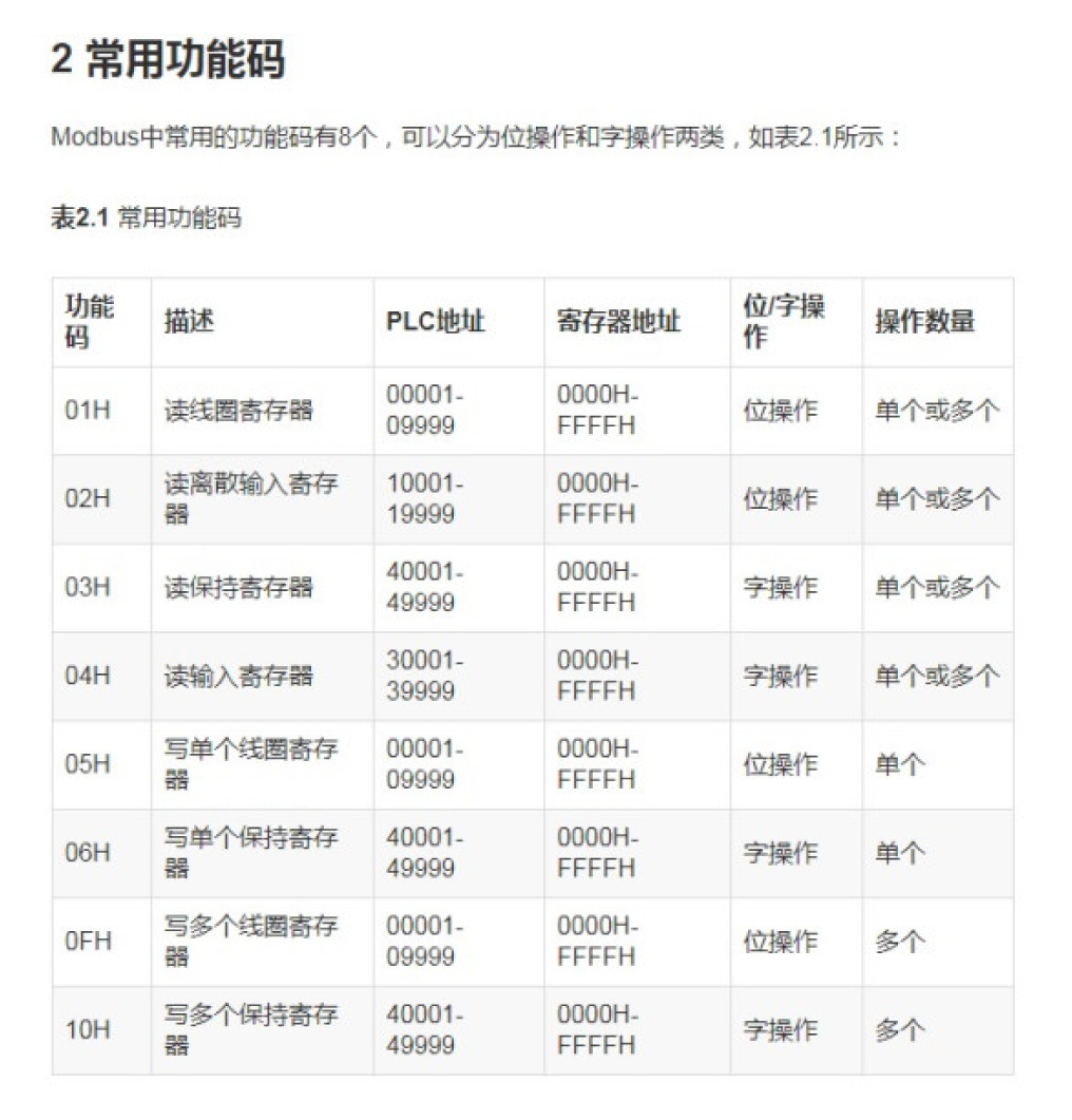
2.3.modbus function code
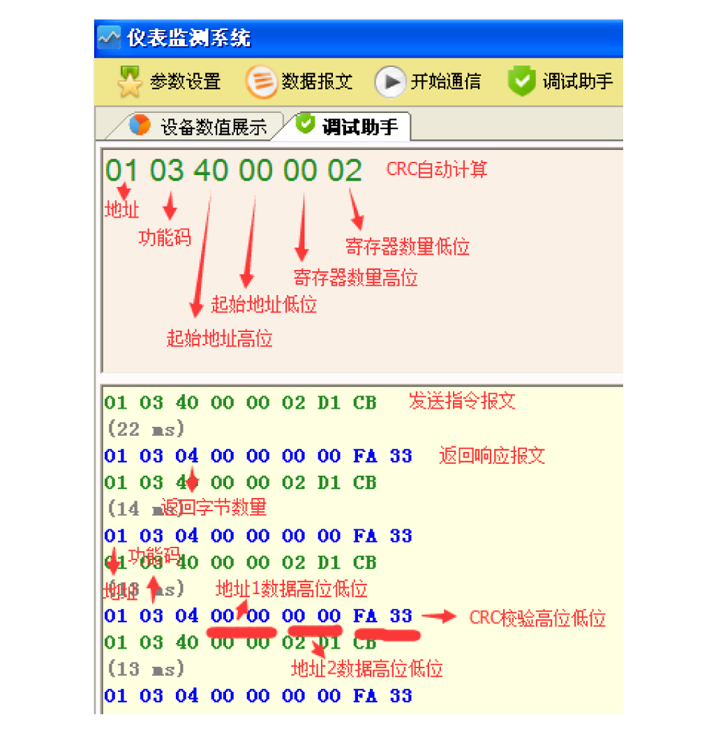
 2.4. Communication message example